This case study investigates how to use the Bolted Connection Designer (BCD) tool to analyse a pre-loaded 6 bolt connection in uniaxial bending.
In order to use the free BCD you will need to register with the Digitool site. After registration you will be redirected to the Digitool homepage and you will be able to launch the BCD from the Digitools menu. A new bolted connection can be created by selecting “New Connection” from the Action Menu. You will then be presented with the Add Connection Screen. On this screen the connection and material properties are set along with the applied forces and moments for the connection.
For this particular problem the connection properties are shown in the image below (Fig 1). Initially the thread chosen is an estimate and can be changed later to ensure the bolts are designed with the required factor of safety. The bolt length is stipulated at this stage and is broken down into two lengths. The unthreaded length is the length of bolt shank in the grip. The threaded length is the length of thread in the grip. The grip length is defined by the combined thickness of all of the joint members which are put in compression by the bolt.
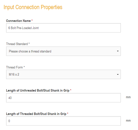
Fig 1 – Connection Properties
The forces and moments applied to the connection are prescribed when the connection is set up. See the image below (Fig 2) for the values used in this case study :-
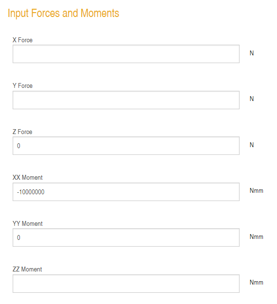
Fig 2 – Forces and Moments Applied to the Bolted Connection
It is important to note that there is a sign convention used in the bolt design software. See the image below (Fig 3):-
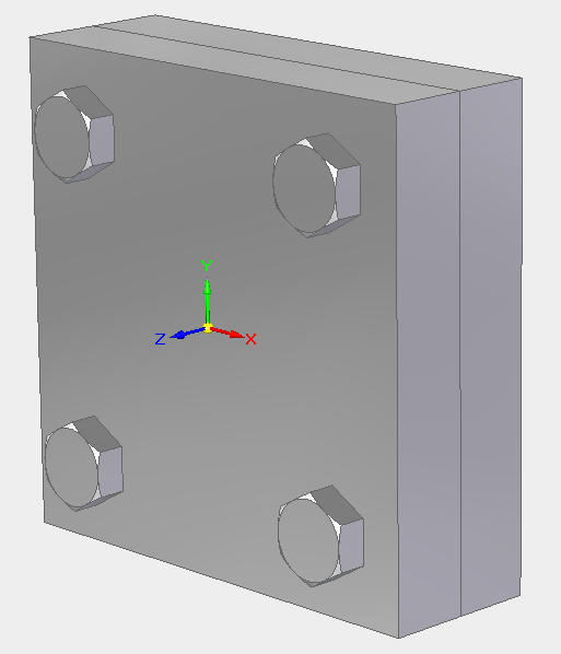
Fig 3 – Sign Convention
Forces are positive when they act in the direction of the arrows shown in the figure above. Moments are positive when they act in a clockwise direction looking down the arrow towards the centre of the triad.
The material properties for the connection are defined below :-
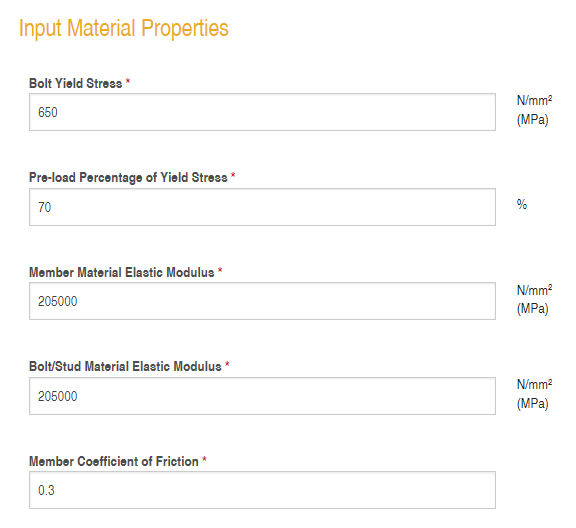 Fig 4 – Material Properties
The calculation is executed when a bolt is first added to the connection and then for all additional bolts thereafter. The bolted joint in this case study is defined by the bolt positions below:-
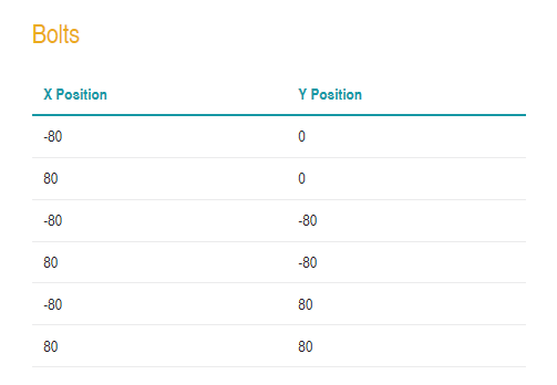 Fig 5- Bolt Positions
After the last bolt is added you can then check the bolt stress for this bolted joint by clicking on the “Display Stress” link from the Connection View page.
The output should look like the following image (Fig 6):-
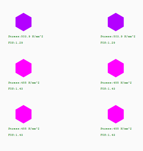 Fig 6 – Bolt Stress Plot
As can be seen from Fig 6 this connection would be satisfactory and would sustain the applied moment. All of the properties used to initialise this connection can be altered and the stress plot will update in response to any changes.