The Solidworks Simulation package is an industry standard finite element analysis application.
In this article I am going to consider a DN100 bolted flange as a basis for comparison. I have analysed this flanged connection for a single load case in both Simulation (SS) and the Digitool Bolted Connection design (BCD) tool. I will then compare the results of these two methods and explain my findings.
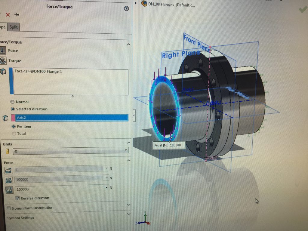
The assembly has been constrained at the right hand end in all degrees of freedom, as denoted by the green arrows. The flange joint face has a frictionless contact with a friction coefficient of 0.12. A vertical force of 100000 N is applied to the left hand pipe at the cut surface, which generates shear and tensile forces in the bolts. At each bolt hole location, a bolt connector is applied and the model is then meshed and processed. Mesh dependency checks and convergence studies were performed to ensure meaningful results.
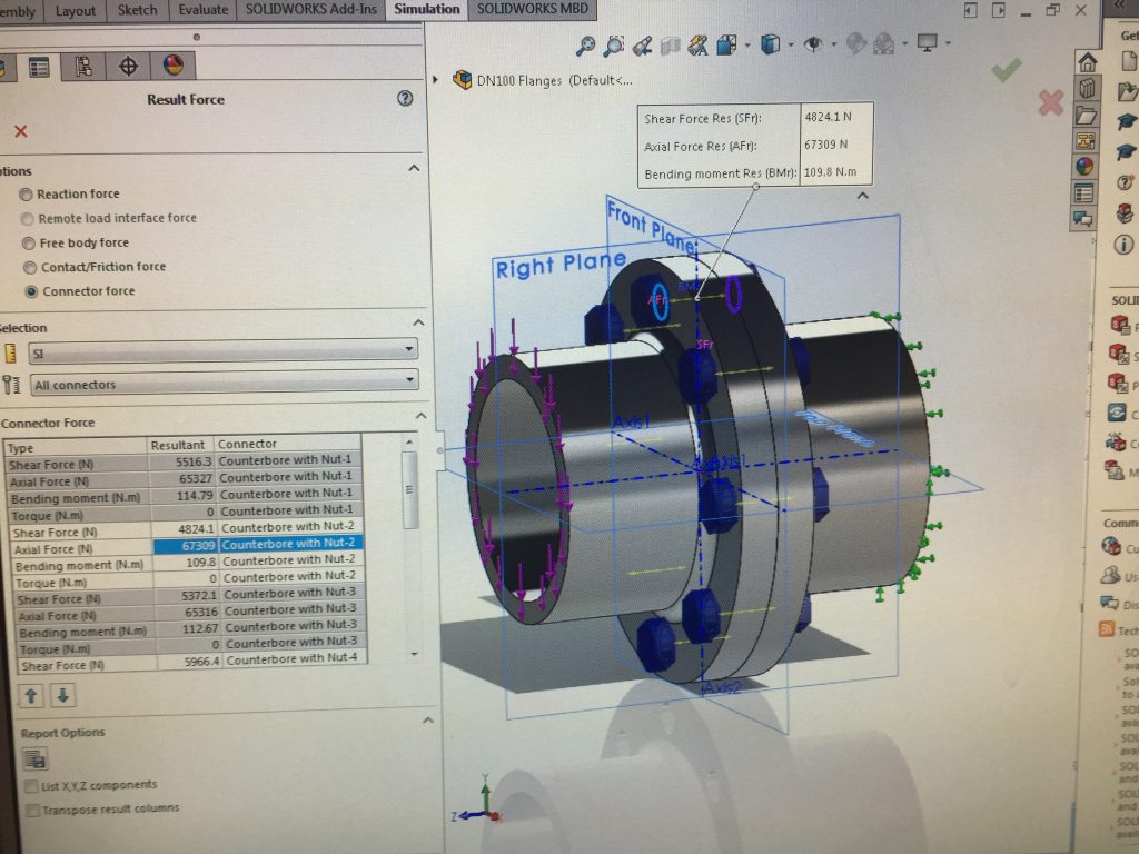
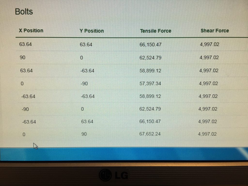
Rather intuitively the bolt with the highest loading is at the top dead centre position of the flange. The axial load is 67309 N and the shear force is 4824.1 N. The principle stresses are then calculated and combined using the Von Mises equation to give the equivalent stress.
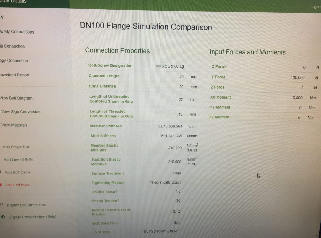
The above two figures show the inputs for the BCD tool, which is set up using the same boundary conditions as the FEA model.
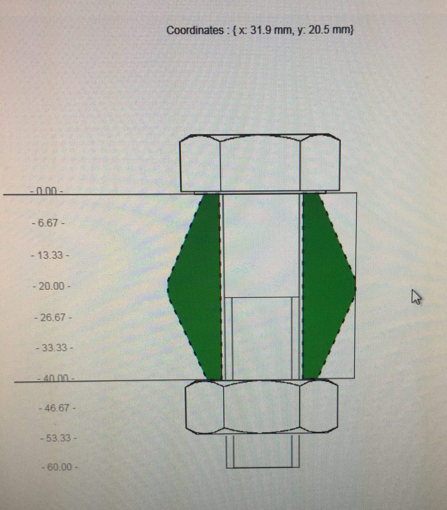
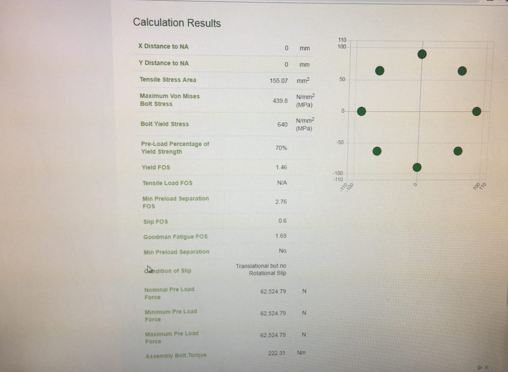
The above cross section from BCD illustrates the geometric volume of clamped material which is included in the stiffness calculations. It is assumed that the clamped material is a prismatic solid which is symmetrical about its two centre lines and bounded by the hole centre to edge distance. This is a recommendation of VDI 2230 for a multi bolt joint in the absence of a Finite Element Analysis.
As calculated from the values in Fig 2, the FEA bolt stress is (67309^2 + 3*4824^2)^0.5/155 = 435 MPa. This compares very well to the BCD calculated stress of 439.8 MPa.